AMPS Phase vs. AMPS Peak

AMPS Phase vs. AMPS Peak
Step motor terminology can be confusing for all engineers; both at the novice and the advanced level. With so much technical jargon floating around, it’s hard to stay up to date with everything. However, getting to know the terminology that is associated with your specific application is of the utmost importance.
For engineers who use step motors in a current-controlled method, which is the case for almost all bipolar drivers, amperage is a key component to take into consideration. When one specification is so essential to the motor’s performance, it is imperative that all terminology that is associated with it is also understood. In the case of step motors, they are almost always labeled with an Amps/Phase rating, also known as Amps RMS or average current. This might seem simple enough, but then, step motor and driver manufacturers will throw in a term like “Amps Peak” current into the mix and cause some confusion. So what does this all mean?
Let’s first understand why the current rating is important when using current-controlled systems. Drivers will control when and how much current each motor phase will receive. You can imagine it as two switches for the two phases of a bipolar step motor. These switches will turn on and off in a sequence in order to get the motor to step. Each change is equal to one step. Furthermore, with each change, current will flow in the motor (rise) then flow out (deplete) due to the fact that the coils act like storage for power.
Current ratings stem from overall I2R power and the internal step motor coils have a resistance rating. Since this is based on the windings, we choose I, current, to be a value such that I2 R power does not exceed standard wattage ratings per motor size. Beyond the standard ratings, you’ll end up with a burnt motor.
Finally, what exactly is Amps/Phase, Amps RMS and Amps Peak? Earlier we mentioned the switching sequence in order to make a motor step; the sequence for both A and B is shown below. Recall in circuits, “negative” simply means current is flowing in an opposite direction.
| PHASE A | PHASE B | DETAIL | COORDINATES (*) |
|---|---|---|---|
| -ON | ON | Moves to 1.8° | #1 (-1, -1) |
| -ON | OFF | Moves to 3.6° | #2 (-1.41, 0) |
| -ON | -ON | Moves to 5.4° | #3 (-1, -1) |
| OFF | -ON | Moves to 7.2° | #4 (0, -1.41) |
| ON | -ON | Moves to 9.0° | #5 (1, -1) |
| ON | OFF | Moves to 10.8° | #6 (1.41, 0) |
| ON | ON | Moves to 12.6° | #7 (1, 1) |
| OFF | ON | Moves to 14.4° | #8 (0, 1.41) |
(*)Another way of depicting the ON, -ON, and OFF, -OFF is to show it as Phase A as the X-Coordinate, and Phase B as a Y-Coordinate:
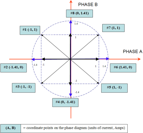
Why are some values 1 and others are 1.41? Take a look at how we got the value 1.4. Look at quadrant I, position #7:
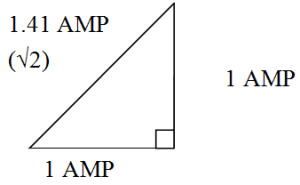
Recall from geometry a right-angle triangle is a 1-1-√2 combination. The √2, or 1.4 value is also the radius of the dotted circle shown above. Therefore, during certain steps, A or B will receive 1.4 Amps of current.
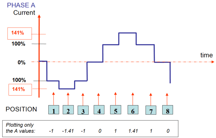
Furthermore, if we plot out the change in current values for the A Phase only, it will look something like this:
What is RMS Current?
Since the current waveform shown above is continuously changing, we need to be able to communicate what the average current is for that particular step motor. RMS is a statistical measurement of the magnitude when the values are always changing.

Beginning at position #1 for the A phase, we calculate: [(12 + 1.412 + 12 + 02 + 12 + 1.412 + 12 + 02) / 8] 1/2 = 0.999 or 1.0 Amp RMS
Theoretically, the average amount of current a motor will receive based on the above graphs and charts, is 1.0 Amps RMS.
What Is Amp/Phase?
This tells us how much average current each winding or phase can handle without heating up and burning the motor. This value is the same value as the Amp RMS rating. The labels on the motor and the datasheet of the motors will list Amp/Phase. In our example shown above, the Amp/Phase and Amp RMS values are 1.0 Amp. The peak value is 1.4 Amp Peak.
What Is Peak Current?
The motor current could potentially reach 1.41 Amps for a split second. The peak of this graph is at 141%. This is what peak current is. Drivers and controller products only care about what the max current will be at any given point, therefore, they refer to current in terms of the peak. Recent changes are being made since most motion control users understand current in terms of what the motor can handle, thus adding both specs on the driver datasheets.
What’s the correlation between it all?
Amps/Phase * 1.41 = Amps Peak current. Regardless of whether you remember the reason behind the 1.41 value, it’s crucial to understand this relationship because in most manufacturers, drivers only care about what peak value it can output. And step motors only care about listing the Amps/Phase value. As long as you understand what the difference is, you will be able to talk in the same language to both driver manufacturers and step motor manufacturers.
News
Continue Reading
Design Accuracy Comparison 0.9° vs. 1.8° Stepper Motors
Often times, when an engineer is selecting a step motor for his or her application, one important decision that needs to be made, is whether or not to choose a 0.9° or a 1.8° step motor. When making a decision of this magnitude, two factors will invariably come into play: performance and price. With the ever-increasing role of competition in today’s motion control industry, both performance and price are major difference makers in every decision.

Customized OEM Electric Motors at Standard Product Costs
Imagine being in the middle of your latest design project when you realize that no one makes a motor that will fulfill the needs of your end product. What’s worse is that there’s no additional budget dollars to pay for a custom component. You sense you’re dead in the water. Your design is an innovation over one of your highly profitable systems. You sell thousands of units per month. The end product has a history, but even if it didn’t, estimated sales in the thousands means that you’re buying OEM quantities of every component—including the motors you’ll need. Could that lower the cost of a custom motor to the point of breaking even?


