Methods for Increasing Accuracy in Stepper Motors
Methods for Increasing Accuracy in Stepper Motors
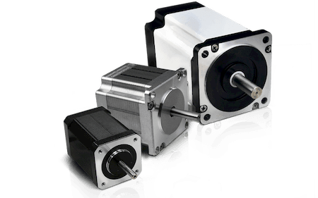
It is well known in the engineering field that mechanical tolerances have a major effect on precision and accuracy for every type of device imaginable regardless of its use. This fact is also true of stepper motors. For example, a standard built stepper motor has a tolerance level of about ±5 percent error per step. These are non-accumulative errors by the way. Most stepper motors move 1.8 degrees per step, which results in a potential error range of 0.18 degrees, even though we’re talking about 200 steps per rotation (see Figure 1).
Micro Stepping for Accuracy
With a standard, non-cumulative, accuracy of ±5 percent, the first and most logical way to increase accuracy is to microstep the motor. Micro stepping is a method of controlling stepper motors that achieves not only a higher resolution but smoother motion at low speeds, which can be a big benefit in some applications.
Let’s start with our 1.8-degree step angle. This step angle means that as the motor slows each step becomes a larger portion of the whole. At slower and slower speeds, the relatively large step size causes cogging in the motor. One way to alleviate this decreased smoothness of operation at slow speeds is to reduce the size of each motor step. This is where microstepping becomes an important alternative.
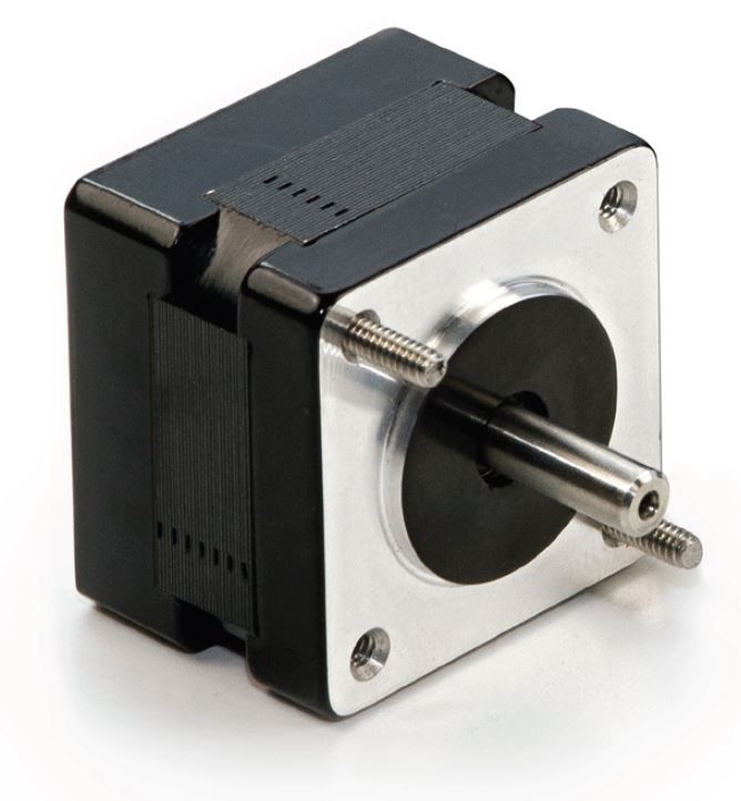
Microstepping control divides each full step into smaller steps to help smooth out the motor’s rotation—especially at slow speeds. Normal microstepping levels are 2, 4, 8, 10, 16, 32, 64, etc. up to 256 (see Figure 2). Although, it is generally believed that anything over about 10 does not yield significantly greater benefits to accuracy, let’s consider what it would mean to microstep at 256 times. In this case, we divide our 1.8-degree step 256 times. This provides a step angle of 0.007 degrees (1.8 ÷ 256), or a whopping 51,200 microsteps per revolution. Even at low speeds, this huge increase in steps greatly reduces cogging. So, how is this done?
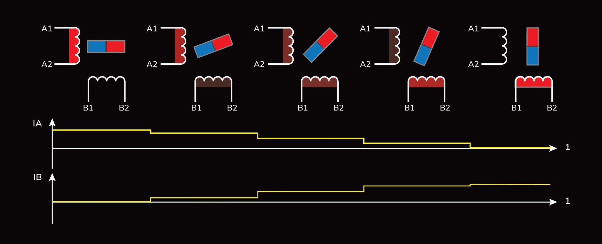
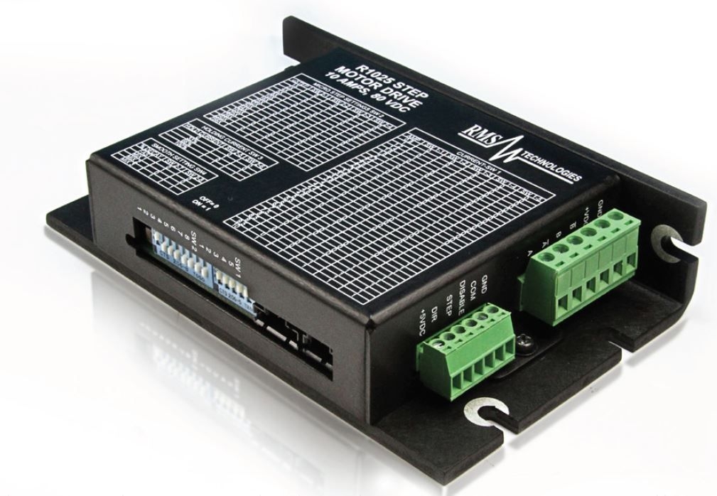
Micro stepping is achieved by using pulse-width modulated (PWM) to control the current to the motor windings. What happens is that the motor driver delivers two voltage sine waves to the motor windings, each of which is 90 degrees out of phase with the other. So, while current increases in one winding, it decreases in the other winding to produce a gradual transfer of current, which results in smoother motion and more consistent torque production than one will get from a standard full step (or even common half step) control (see Figure 3).
When deciding on an increase in accuracy based on microstepping control, engineers have to consider how this affects the rest of the motor characteristics. While the smoothness of torque delivery, low-speed motion, and resonance might be improved using microstepping, typical limitations in control and motor design prevent them from reaching their ideal overall characteristics. Due to the operation of a stepper motor, microstepping drives can only approximate a true sine wave. This means that some torque ripple, resonance, and noise will remain in the system even though each of these is greatly reduced in a microstepping operation.
Torque production from a stepper motor with microstepping control is only about 70 percent of the torque produced with full-step control.
You might also want to consider that the accuracy of the motor is dependent on the step size of the motor itself (without microstepping). For example, a motor with a 0.9-degree step angle is more accurate than a 1.8-degree motor because there are mechanically more steps introduced (400 for 0.9 and 200 for 1.8 per revolution). Looking at the rotor design of 1.8° and 0.9° motors, it can be seen that a 1.8° motor has 50 rotor teeth whereas a 0.9° step motor has 100 rotor teeth. This alone gives 0.9° motors higher torque stiffness and thus, higher accuracy. During microstepping, you are not necessarily increasing the accuracy, but you are increasing the resolution.
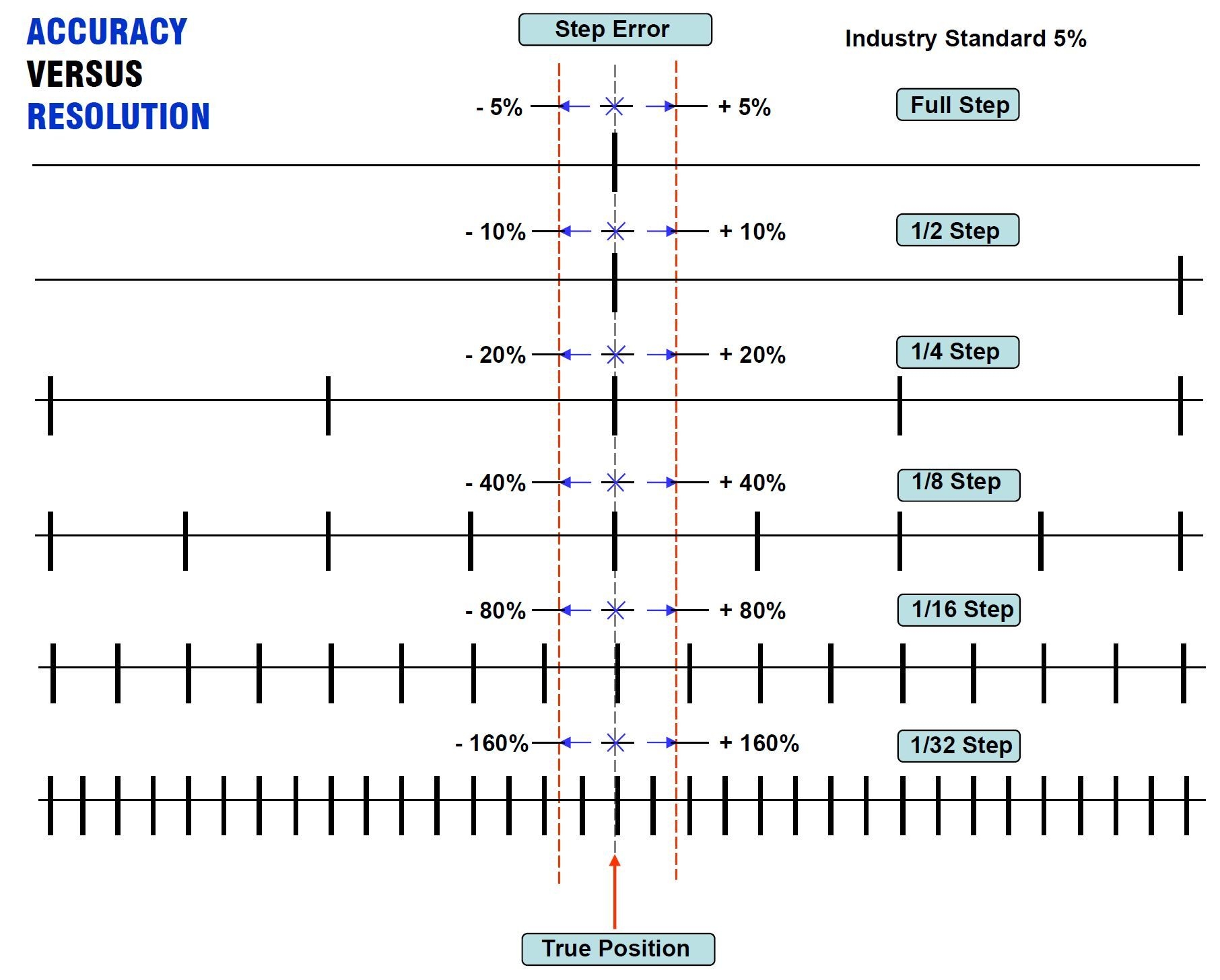
As illustrated in Figure 4, when you begin to microstep you get an increase in step error as a result of having more steps. But if you look at the step error increase, you can see that the positional error remains the same regardless if it's full stepping or 1/32 stepping. This is due to the inherent mechanical properties of the motor. The step error percentage is so high because you have to remember in microstepping you are essentially “balancing” the current between different phases in between the natural full step. At any given point, the step can swing in either direction if some external force is applied to it. In comparison to the step size, for example, 1/32, you will receive a much higher range of error if something external were to happen. The bottom line is that the accuracy of the motor doesn’t increase, but you do get a large increase in resolution, which assists with the other topics mentioned here. Mitigating issues such as vibration and cogging could potentially increase accuracy during microstepping.
When designing a system, engineers must take everything into consideration and weigh the pros and cons. So, consider that while microstepping is sometimes considered a good alternative to mechanical gearing because it does not introduce backlash into the system or reduce the system’s maximum speed, mechanical gearing has the ability to multiply the torque from the motor and increases its position-holding capability.
Mechanical Accuracy
Another mechanical adjustment to gain accuracy in your stepper motor is to use a smaller inertia load. If the motor is attached to a large inertia when it tries to stop, the load will cause some slight over-rotation. Because this is often a small error, the motor controller can be used to correct it.
Finally, we turn back to the controller. This method may take some engineering effort. In order to improve accuracy, you may want to use a controller that is specifically optimized for the motor you have chosen to use. This is a very precise method to incorporate. The better the controller’s ability to manipulate the motor current precisely, the more accuracy you can get from the stepper motor you are using. This is because the controller regulates exactly how much current the motor windings receive to initiate the stepping motion.
Precision in motion systems is a common requirement depending on the application. Understanding how the stepper system works together to create precision allows an engineer to take advantage of the technologies that are available, including those used in the creation of the mechanical components of each motor.
News
Continue Reading

Rapid DC Motor Manufacturing For Fight Against COVID-19
With the COVID-19 outbreak, the demand for medical equipment has been quickly increasing. A lot of these devices depend on their precise motors to operate. In order to support the ongoing efforts to combat COVID-19, we are prioritizing the production and supply of our motors to support companies producing medical devices critical to the treatment of COVID-19 patients.
Customize winding of Hybrid Stepper Motors to achieve higher efficiency
There are plenty of modifications we can make to a Hybrid Stepper Motor to optimize the motor’s performance to your specific application, and one of those modifications is customizing the motor’s windings.


