Selecting the Right Stepper Motor for Medical Applications

Selecting the Right Stepper Motor for Medical Applications
Medical applications often have the added concern that people’s lives may be in jeopardy if the equipment doesn’t work properly. Engineers working in this field of expertise must consider quality and longevity every step of the way. Therefore, when selecting a stepper motor for a medical device, engineers focus on the specific critical factors needed for the device prior to making a purchase. For example, a systolic pump may require high accuracy and a small footprint while a blood sampler used in a laboratory may need to be exceptionally quiet. As indicated, the requirements for stepper motors vary from device to device, yet there are several key factors that should always be considered.
Footprint
Miniaturization is a continual concern for many industries and one of the major trends over recent years. This is particularly true when considering medical device design. As equipment gets exponentially smaller, the challenges of designing devices to fit this equipment gets bigger.
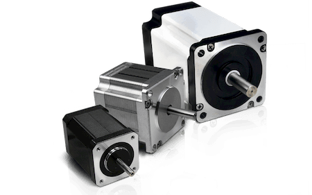
In general terms, stepper motor manufacturers adhere to various NEMA frame sizes. NEMA standards govern motor dimensions, including the size of the front flanges used to mount motors to devices. NEMA sizes for stepper motors range from NEMA- 8 to NEMA-42. For comparison, NEMA-8 motors with 0.8-in.2 front flanges generate about 2 to 3 oz-in. of torque, while NEMA-42 motors have 4.2-in.2 front flanges and output over 2,000 oz-in. of torque.
On the occasion when motors can be located that are small enough for handheld devices or devices that must be used in the home, these NEMA products lack the critical specifications necessary to perform properly, such as providing enough torque or speed needed for the device to be competitive in the market. The option used by many medical device manufacturers is to design-in a large-framed stepper motor, which means they have to shrink all the other components. This approach often requires special brackets and mounting hardware. Motion control in this small a scale is the challenging bottleneck that forces engineers to compromise on the footprint of their device time and again.
What about NEMA 6 size motors, you might ask. Of the manufacturers that have tried to create a NEMA 6 size hybrid stepper motors in the past—and there are very few of them—most have failed, suggesting that the NEMA 6 frame size is too small to provide the performance these applications require.
Think Hybrid
Medical applications exhibit space constraints in most cases. Therefore, the smaller the available motor, the better for the design engineer. Smaller motors require less power during operation, so they save on energy costs. But there are drawbacks to small motors as well, the major one being a decrease in torque. And although you might think smaller means less expensive, building small and precise motors typically costs more. All this means is that design engineers wishing to incorporate miniature stepper motors into their medical equipment designs, must weigh the trade-offs.
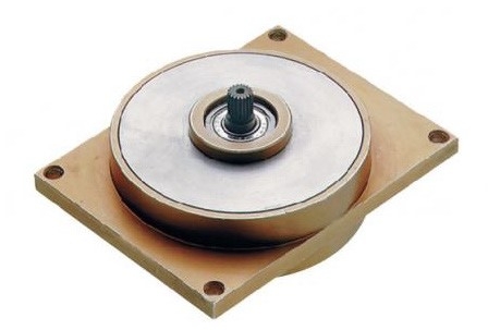
One stepper-motor manufacturer, Lin Engineering (Morgan Hill, CA) incorporates innovative design methods to shrink motor size while simultaneously increasing torque. Their NEMA 6 hybrid stepper motor was custom designed by their engineers, who are experienced in several related disciplines. The team was able to succeed in creating a field-tested hybrid stepper motor technology that not only delivers plenty of usable dynamic torque at high speed, it provides a high level of accuracy. Let’s discuss how they were able to design and manufacture such a device.
By increasing the step angle from a typical 1.8 degrees to 3.46 degrees, the company was able to achieve nearly twice the holding torque as the closest competing design, and nearly four times more holding torque—at up to 2.1 oz-in) than a conventional permanent magnet stepper motor of similar size (which tops out at 0.5 oz-in). Further, a typical PM motor delivers about 20 steps per revolution—a step angle of 18 degrees.
The 3.46 degree motor is able to deliver 5.7 times higher resolutions than a typical PM motor. Higher-resolution translates directly into higher precision for your application, providing the benefits of a hybrid stepper with none of the drawbacks of a PM motor. Add to this change in step angle a low inertia rotor design and the motor is able to achieve over 1 oz-in of dynamic torque at nearly 8,000 rpm—delivering similar speed performance as that of a standard brushless DC motor.
When it comes to motor size, length is often critical for fitting the motor into medical devices. NEMA standards do not account for length and length can vary among motor manufacturers and change with redesigns and upgrades. Hybrid stepper motors are easily adjusted for exactly what the customer requires.
Generally, stepper motors come with a standard square flange and mount to a bracket. But for some motors, especially modular ones, there is a greater demand custom housings. For example, a handheld liposuction device needed a stepper motor to create suction. Lin Engineering was able to use a modular motor design, which they molded into a plastic housing that did not require screws to mount the motor. This saved room and kept the device small enough to be handheld.

Maintaining Accuracy
Stepper motors rotate in terms of degrees. Each step can be in increments of 1.8°, 0.9°, or even 0.45°. This is the inherent and natural step the motor takes. When microstepped, motors are forced to take even finer increments per move. A 0.9 degree motor can be made to step every 0.45 degrees, which is called half-stepping. And 64 microstepping a motor divides the 0.9 degrees into 64 steps of 0.014 degrees each. Microstepping is typically handled by the driver electronics.
Because all stepper motors have some step error, engineers naturally choose motors with the least amount of error whenever possible. Step error is measured in increments of arc minutes—where 1 arc minute equals 0.0167 degree. The industry average error for a 0.9 degree stepper motor at 64 microstepping is 0.075 degrees (4.5 arc minutes), while Lin Engineering’s 0.9 degree stepper motors averages only 0.025 degrees (1.5 arc minutes).
Whisper Quiet
Stepper motors can stop and hold position at any location a program tells it to even though they take steps when moving. At certain speeds, stepper motors resonate and vibrate loudly, which can turn into jerky motion. This noise is due to the rotational frequency, in steps, matching the motor’s inherent resonant frequency. This resonant frequency is generated with each step the motor takes.
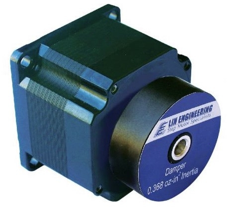
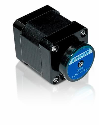
There are methods used that either eliminate or diminish the noise a motor makes. Two major factors determine a stepper motor’s resonant speed: torque stiffness and inertia. Changing a motor’s torque properties shifts the resonant point to a lower or higher speed. This can be done by changing the driver’s power supply voltage or the current delivered by the driver. Increasing either of these values shifts the resonant frequency to a higher speed. Changing the inertia of the load on the motor also shifts the resonant frequency, which can be accomplished by adding a damper to the rear side of the stepper motor. If the resonant sweet spot is high enough, the motor will never see it and, therefore, generate less noise.
Motor noise can stem from other causes, including mechanical issues, electrical issues, or using the wrong motor. The first of these elements include the front and rear bearings, which fit inside the motor’s end caps and are installed on the motor’s shaft. Most noisy motors have poorly fitted bearings in the rear cap, evident by defects in the motor manufacturer’s assembly processes as well as by the motor component’s dimensional tolerances. If quiet operation is vital, ask your motor manufacturer to hold certain tolerances within the bearing bore of the end cap and question how it handles critical dimensions.
Electrical noise is not audible but can be seen on oscilloscopes or other electrical devices within the application. Electrical noise can be caused by an imbalance in the stepper motor’s resistance and inductance caused by a motor being poorly made. Select a motor from a manufacturer that uses quality wire. Or, request that the motor be built with a heavy-build wire. Heavy-build wire is double-coated with protective material. Even if it gets nicked during winding, there is little risk of cutting through both coatings. Simple misapplication, or when users choose motors that create more torque than needed, the device will exhibit higher vibrations and noise. In general, engineers should chooses motors with 20% more torque than their application needs. Anything more is overkill.
Overall Quality
When looking for reliable stepper motors, engineers often request MTBF (mean-time-between-failure) data to ensure the potential motor will last a certain number of cycles. Stepper motors typically have an MTBF of over 20,000 hr of continuous operation. When stepper motors operate at their bearings’ rated axial and radial loads or less with temperatures kept to less than 50°C, stepper motors usually last 20 years, assuming a 50% duty cycle.
So, whether your application involves making intricate cuts within a patient’s eyes, pumping critical bodily fluids, or any other type of medical application, taking a motor’s size, accuracy, smoothness of motion, noise level, quality, and reliability are a must.
News
Continue Reading
Designing and Manufacturing Miniature Stepper Motors
In a world where devices are getting smaller but must still perform like their larger counterparts, designing hybrid stepper motors to be flexible and accurate takes some design expertise.
Tips on How to Reduce Stepper Motor Resonance
Noise reduction can be a challenge when designing in stepper motors for certain applications. This resonant vibration often produces adverse effects that are easily eliminated once you understand what changes to make.


