Request a Quote
R1025 SERIESR1025STEPPER DRIVER
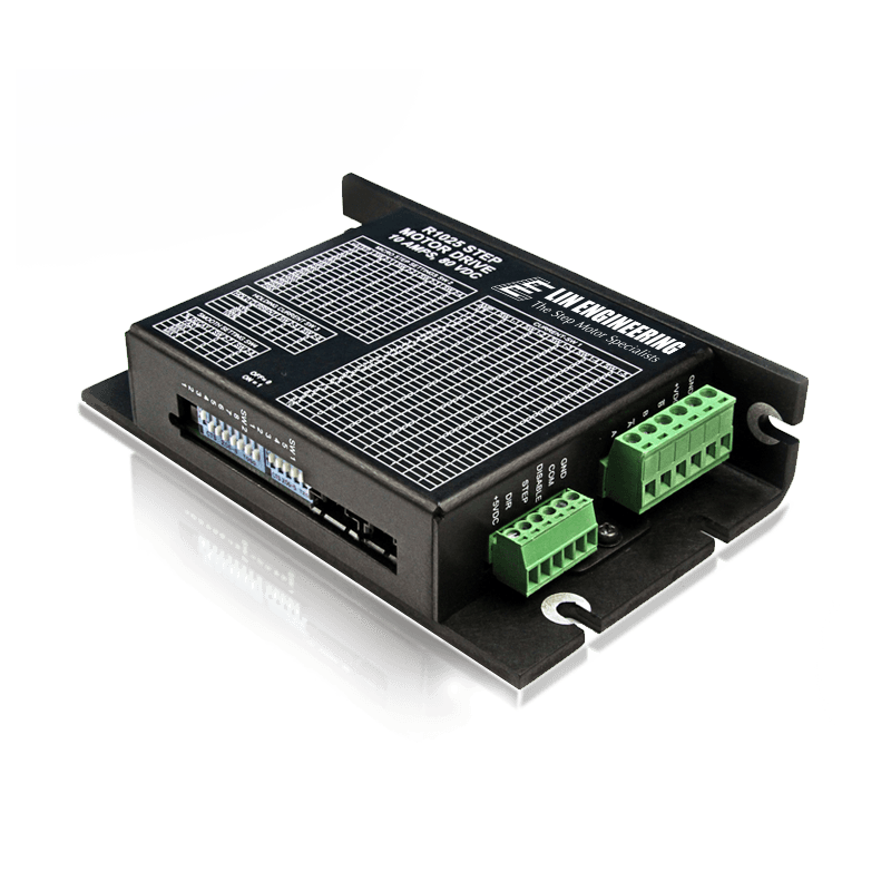
Quick Facts
R1025 Drivers & Controllers
R1025 Drivers & Controllers
Features and Benefits:
- Operates from +12 to 80 VDC
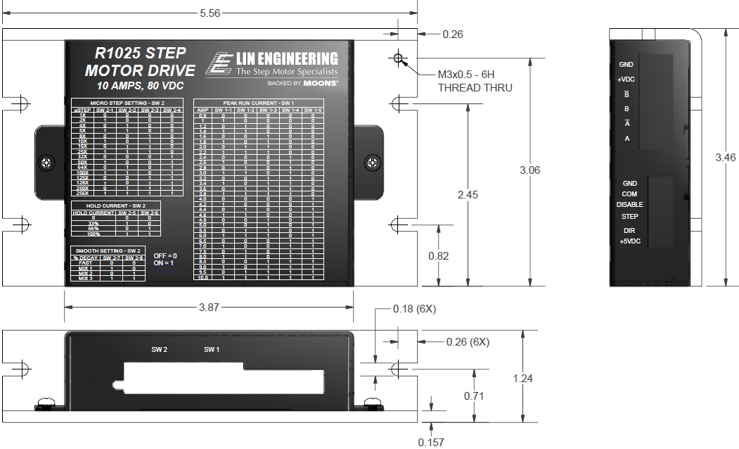
- Selectable run currents from 0.8 to 10 Amps Peak Holding and Running Torque
- Step Resolutions from Full step, 2x, 4x, 5x, 8x, 10x, 16x, 25x, 32x, 50x, 64x, 100x, 125x, 128x, 250x, 256x Microstepping
- Optically isolated inputs that can sink and source (3 to 24 VDC, 16mAmps)
- Selectable Damping modes for smooth motion
- Easy to configure without connecting to PC, utilizes DIP switches (Run and hold current, Step resolution, Smoothness setting)
- Operating temperature of -40C to 85C
- Operates in ambient temperature of -20C to 50C
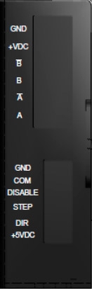
Out Puts
| FUNCTION | PIN NAME | DESCRIPTION | ELECTRICAL SPECS. |
|---|---|---|---|
| POWER/MOTOR | GND | GND. Connect the negative end of Power Supply here | GND |
| +VDC | Power. Connect Positive end of Power Supply here. DO NOT EXCEED MAX VOLTAGE RATING OF 80VDC! | Voltage Input: 12 - 80VDC | |
| B- | Phase B Bar Motor Connection | Phase currents from 0.8 to 10A Peak Current Chopping Frequency: 22KHz | |
| B | Phase B Motor Connection | Phase currents from 0.8 to 10A Peak Current Chopping Frequency: 22KHz | |
| A- | Phase A Bar Motor Connection | Phase currents from 0.8 to 10A Peak Current Chopping Frequency: 22KHz | |
| A | Phase A Motor Connection | Phase currents from 0.8 to 10A Peak Current Chopping Frequency: 22KHz | |
| LOGIC | GND | Logic GND | GND |
| COM (Input) | Opto Common input. Used to Optically Isolate the Input when a separate supply is connected. Connecting the +5VDC will make the Inputs Functional but the Inputs will NOT be Isolated. Note COM needs to be powered either by a separate supply or the +5VDC Pin in order for the Input/Outputs to function. | Voltage: 3 - 24 VDC Max Current: 20mA | |
| DISABLE (Input) | Used to Disable drive. Active Low. A closed connection to GND will Disable the drive. This is a Sink or Source Input | Voltage: 3 - 24 VDC Max Current: 20mA | |
| STEP (Input) | The Step output from a Pulse Generator is Input into this pin. Both an NPN and a PNP type PLC can be used for this input. Refer to Connection Diagrams for help | Voltage: 3 - 24 VDC Max Current: 20mA | |
| DIR (Input) | Used to switch Direction of motor. Active Low. A closed connection to GND will change direction. This is a Sink or Source Input. | Voltage: 3 - 24 VDC Max Current: 20mA | |
| +5 VDC (Input) | Internal +5VDC Output. If Optical Isolation is not desired then it can be connected to COM Pin. DO NOT USE FOR EXTERNAL CIRCUITRY! | Voltage: 5 VDC Max Current: 80mA |
Dimension
Electrical Specifications
• Operates from +12 to 80 VDC • Selectable phase currents from 0.8 to 10.0 Amps Peak
• Isolated inputs: Step, Direction, and Disable • Step frequency (max): 1.0 MHz
• Steps per revolution (1.8° motor): 200, 400, 800, 1600, 2000, 3200, 5000, 6400, 10000, 12800, 25000, 25600, 50000, 51200}
• Microstep Resolutions (1.8° motor): Full step, 2X, 4X, 5X, 8X, 10X, 16X, 25X, 32X, 50X, 64X,125, 128X, 250X, 256X
• Operating Temperature: -20°C to +85°C
DEFAULT SETTINGS
| Direction of Rotation | Counterclockwise |
|---|---|
| Step Resolution | 8x step (3200 steps/rev) |
| Run Current | Motor's rated current or up to 5 Amps Peak if motor is rated for 5 or higher |
| Holding Torque | 0.5 Amp/Phase |
| Smoothness Setting | 2 |
| Step Signal Sensing | Senses on the Rising Edge or positive edge |
| Disable Active | Low or oV signal to disable unit |